Project • Finite Element Analysis • Ansys • Dec 24, 2024
An Initial Look at Finite Element Analysis
Over the winter break I decided to begin learning Finite Element Analysis using Ansys, after being recommended to learn it by colleagues on the Airframe Team at UAARG (University of Alberta Aerial Robotics Group). My first dive into Ansys Mechanical, after completing a basic tutorial, was with a bicycle crank arm that I had designed in SolidWorks. The goal was to find where the highest stress concentrations occur under extreme loading at various extension positions expected while riding.
Context
Self-directed learning • FEA Analysis
Tools
Ansys Mechanical, SolidWorks
Focus
Static structural FEA, mesh refinement
1. Model and Loading
The part was a bicycle crank arm (reference geometry similar to commercial mountain bike cranks). I chose it to investigate stress concentrations under extreme loading at different extension positions. “Extreme loading” was taken as roughly 3000 N static: either acting vertically downwards (negative z) or in the positive x direction (to the right). The load was applied as a bearing load on the smaller hole (pedal location). The material was Aluminum 6061, for its low cost, ease of machining, and common use in bicycle components.
2. Baseline Analysis Results
In Ansys Mechanical I determined the stress concentration distribution, peak stress, and deformation. From the equivalent stress results:
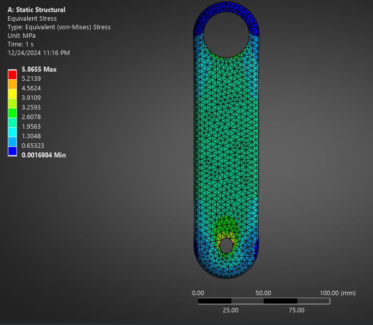
With 3000 N acting vertically downwards, the stress field and peak values were relatively moderate.
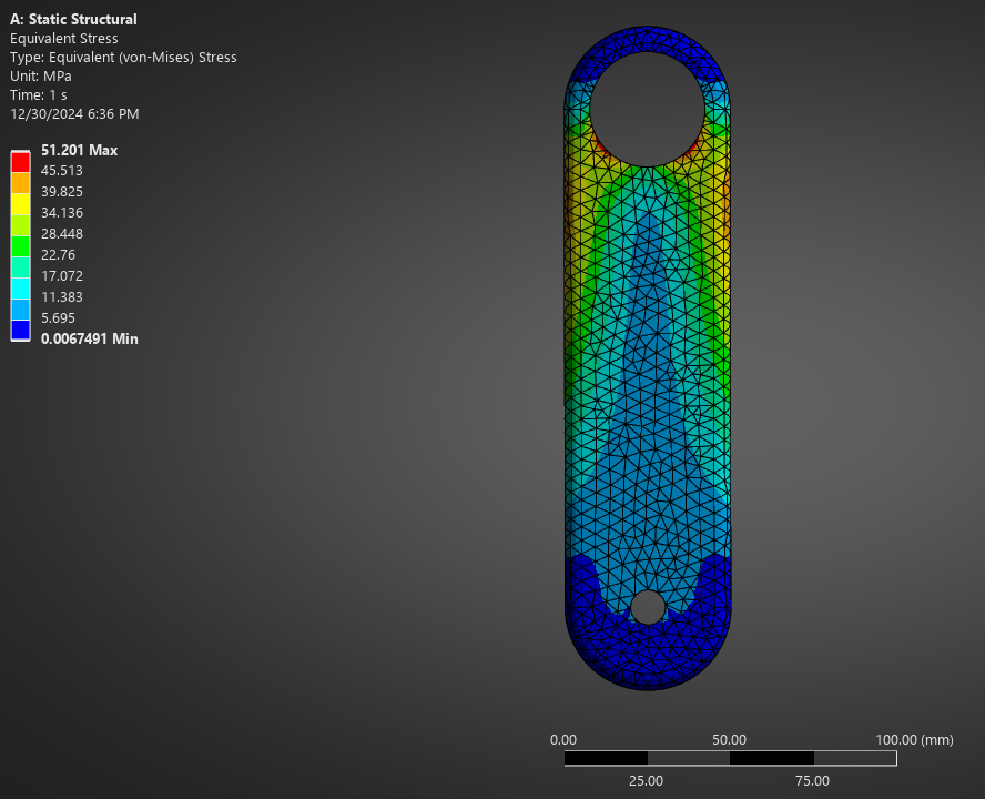
With 3000 N acting to the right, stress was much higher.
Because loading the crank to the right produced the more critical case, I used that loading direction for further design iterations to simplify the analysis.
Equivalent stress distribution with 3000 N acting vertically downwards.
Equivalent stress distribution with 3000 N acting to the right (higher stress).
3. Second Design Iteration – Weight Reduction
A goal of this project was to explore designing a crank that reduces weight while keeping sufficient structural integrity. For learning and curiosity I analyzed a second design with additional material removed (e.g. weight-reduction slots). This iteration saved roughly 10% weight and served mainly to see where new stress concentrations appear.
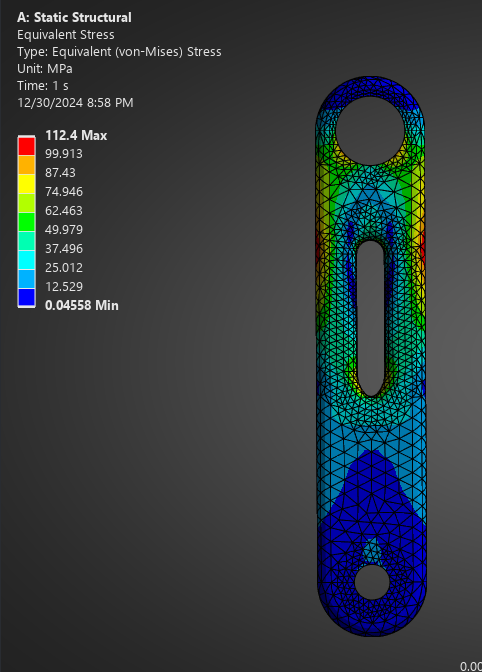
Under the same 3000 N load to the right, the peak stress in the new design almost doubled. The peak was on the outside of the crank, in line with the top corner of the middle weight-reduction slot on both sides. A logical next step would be to vary the width of the crank—wider around the top ends of the slot and slimmer in low-stress regions—but I did not implement that here so that I could focus on learning how to interpret stress distributions and make informed design choices. Additional iterations were run but are omitted for brevity.
Equivalent stress for the weight-reduced design with 3000 N acting to the right.
4. Meshing and Takeaways
Although the analysis was fairly rudimentary, it gave a solid basis for running static structural FEA in Ansys. Beyond that, the project was useful for learning how to build proper meshes. In many analyses—FEA, CFD, heat flow, and others—a good mesh is essential. Here I practiced refining the mesh so that elements behave as continuous where needed; if the body is discontinuous, results can be skewed.
Overall, this first FEA project supplied enough understanding to use Ansys Static Structural for basic studies and to start linking stress results back to design changes, with room to add more iterations and refinements in the future.